Thursday 29 October 2015

Laws of Boolean Algebra

The Laws of Boolean

As well as the logic symbols “0” and “1” being used to represent a digital input or output, we can also use them as constants for a permanently “Open” or “Closed” circuit or contact respectively. A set of rules or Laws of Boolean Algebra expressions have been invented to help reduce the number of logic gates needed to perform a particular logic operation resulting in a list of functions or theorems known commonly as the Laws of Boolean Algebra.
Boolean Algebra is the mathematics we use to analyse digital gates and circuits. We can use these “Laws of Boolean” to both reduce and simplify a complex Boolean expression in an attempt to reduce the number of logic gates required. Boolean Algebra is therefore a system of mathematics based on logic that has its own set of rules or laws which are used to define and reduce Boolean expressions.
The variables used in Boolean Algebra only have one of two possible values, a logic “0” and a logic “1” but an expression can have an infinite number of variables all labelled individually to represent inputs to the expression, For example, variables A, B, C etc, giving us a logical expression of A + B = C, but each variable can ONLY be a 0 or a 1.
Examples of these individual laws of Boolean, rules and theorems for Boolean Algebra are given in the following table.

Truth Tables for the Laws of Boolean

Boolean
Expression
Description Equivalent
Switching Circuit
Boolean Algebra
Law or Rule
A + 1 = 1 A in parallel with
closed = "CLOSED"
universal parallel circuit Annulment
A + 0 = A A in parallel with
open = "A"
universal parallel Identity
A . 1 = A A in series with
closed = "A"
universal series circuit Identity
A . 0 = 0 A in series with
open = "OPEN"
universal series Annulment
A + A = A A in parallel with
A = "A"
idempotent parallel circuit Idempotent
A . A = A A in series with
A = "A"
idempotent series circuit Idempotent
NOT A = A NOT NOT A
(double negative) = "A"
  Double Negation
A + A = 1 A in parallel with
NOT A = "CLOSED"
complement parallel circuit Complement
A . A = 0 A in series with
NOT A = "OPEN"
complement series circuit Complement
A+B = B+A A in parallel with B =
B in parallel with A
absorption parallel circuit Commutative
A.B = B.A A in series with B =
B in series with A
absorption series circuit Commutative
A+B = A.B invert and replace OR with AND   de Morgan’s Theorem
A.B = A+B invert and replace AND with OR   de Morgan’s Theorem
The basic Laws of Boolean Algebra that relate to the Commutative Law allowing a change in position for addition and multiplication, the Associative Law allowing the removal of brackets for addition and multiplication, as well as the Distributive Law allowing the factoring of an expression, are the same as in ordinary algebra.
Each of the Boolean Laws above are given with just a single or two variables, but the number of variables defined by a single law is not limited to this as there can be an infinite number of variables as inputs too the expression. These Boolean laws detailed above can be used to prove any given Boolean expression as well as for simplifying complicated digital circuits.
A brief description of the various Laws of Boolean are given below with A representing a variable input.

Description of the Laws of Boolean Algebra

  • Annulment Law – A term AND´ed with a “0” equals 0 or OR´ed with a “1” will equal 1.
  •  
    • A . 0 = 0    A variable AND’ed with 0 is always equal to 0.
    • A + 1 = 1    A variable OR’ed with 1 is always equal to 1.
  •  
  • Identity Law – A term OR´ed with a “0” or AND´ed with a “1” will always equal that term.
  •  
    • A + 0 = A   A variable OR’ed with 0 is always equal to the variable.
    • A . 1 = A    A variable AND’ed with 1 is always equal to the variable.
  •  
  • Idempotent Law – An input that is AND´ed or OR´ed with itself is equal to that input.
  •  
    • A + A = A    A variable OR’ed with itself is always equal to the variable.
    • A . A = A    A variable AND’ed with itself is always equal to the variable.
  •  
  • Complement Law – A term AND´ed with its complement equals “0” and a term OR´ed with its complement equals “1”.
  •  
    • A . A = 0    A variable AND’ed with its complement is always equal to 0.
    • A + A = 1    A variable OR’ed with its complement is always equal to 1.
  •  
  • Commutative Law – The order of application of two separate terms is not important.
  •  
    • A . B = B . A    The order in which two variables are AND’ed makes no difference.
    • A + B = B + A    The order in which two variables are OR’ed makes no difference.
  •  
  • Double Negation Law – A term that is inverted twice is equal to the original term.
  •  
    • A = A     A double complement of a variable is always equal to the variable.
  •  
  • de Morgan´s Theorem – There are two “de Morgan´s” rules or theorems,
  •  
  • (1) Two separate terms NOR´ed together is the same as the two terms inverted (Complement) and AND´ed for example, A+B = A. B.
  •  
  • (2) Two separate terms NAND´ed together is the same as the two terms inverted (Complement) and OR´ed for example, A.B = A +B.
 
Other algebraic Laws of Boolean not detailed above include:
  • Distributive Law – This law permits the multiplying or factoring out of an expression.
  •  
    • A(B + C) = A.B + A.C    (OR Distributive Law)
    • A + (B.C) = (A + B).(A + C)    (AND Distributive Law)
  •  
  • Absorptive Law – This law enables a reduction in a complicated expression to a simpler one by absorbing like terms.
  •  
    • A + (A.B) = A    (OR Absorption Law)
    • A(A + B) = A    (AND Absorption Law)
  •  
  • Associative Law – This law allows the removal of brackets from an expression and regrouping of the variables.
  •  
    • A + (B + C) = (A + B) + C = A + B + C    (OR Associate Law)
    • A(B.C) = (A.B)C = A . B . C    (AND Associate Law)

Boolean Algebra Functions

Using the information above, simple 2-input AND, OR and NOT Gates can be represented by 16 possible functions as shown in the following table.
Function Description Expression
1. NULL 0
2. IDENTITY 1
3. Input A A
4. Input B B
5. NOT A A
6. NOT B B
7. A AND B (AND) A . B
8. A AND NOT B A . B
9. NOT A AND B A . B
10. NOT A AND NOT B (NAND) A . B
11. A OR B (OR) A + B
12. A OR NOT B A + B
13. NOT A OR B A + B
14. NOT OR (NOR) A + B
15. Exclusive-OR A.B + A.B
16. Exclusive-NOR A.B + A.B

Laws of Boolean Algebra Example No1

Using the above laws, simplify the following expression:  (A + B)(A + C)
Q = (A + B).(A + C)  
  A.A + A.C + A.B + B.C – Distributive law
  A + A.C + A.B + B.C – Idempotent AND law (A.A = A)
  A(1 + C) + A.B + B.C – Distributive law
  A.1 + A.B + B.C – Identity OR law (1 + C = 1)
  A(1 + B) + B.C – Distributive law
  A.1 + B.C – Identity OR law (1 + B = 1)
Q = A + (B.C) – Identity AND law (A.1 = A)
 
Then the expression:  (A + B)(A + C) can be simplified to A + (B.C) as in the Distributive law.

Logic Gate Truth Tables

Logic Gate Truth Tables

As well as a standard Boolean Expression, the input and output information of any Logic Gate or circuit can be plotted into a standard table to give a visual representation of the switching function of the system. The table used to represent the boolean expression of a logic gate function is commonly called a Truth Table. A logic gate truth table shows each possible input combination to the gate or circuit with the resultant output depending upon the combination of these input(s).
For example, consider a single 2-input logic circuit with input variables labelled as A and B. There are “four” possible input combinations or 22 of “OFF” and “ON” for the two inputs. However, when dealing with Boolean expressions and especially logic gate truth tables, we do not general use “ON” or “OFF” but instead give them bit values which represent a logic level “1” or a logic level “0” respectively.
Then the four possible combinations of A and B for a 2-input logic gate is given as:
  • Input Combination 1. – “OFF” – “OFF” or ( 0, 0 )
  • Input Combination 2. – “OFF” – “ON” or ( 0, 1 )
  • Input Combination 3. – “ON” – “OFF” or ( 1, 0 )
  • Input Combination 4. – “ON” – “ON” or ( 1, 1 )
Therefore, a 3-input logic circuit would have 8 possible input combinations or 23 and a 4-input logic circuit would have 16 or 24, and so on as the number of inputs increases. Then a logic circuit with “n” number of inputs would have 2n possible input combinations of both “OFF” and “ON”.
So in order to keep things simple to understand, in this tutorial we will only deal with standard 2-input type logic gates, but the principals are still the same for gates with more than two inputs.
Then the Truth tables for a 2-input AND Gate, a 2-input OR Gate and a single input NOT Gate are given as:

2-input AND Gate

For a 2-input AND gate, the output Q is true if BOTH input AAND” input B are both true, giving the Boolean Expression of: ( Q = A and B ).
Symbol Truth Table
boolean algebra AND gate truth table A B Q
0 0 0
0 1 0
1 0 0
1 1 1
Boolean Expression Q = A.B Read as A AND B gives Q
Note that the Boolean Expression for a two input AND gate can be written as: A.B or just simply AB without the decimal point.

2-input OR (Inclusive OR) Gate

For a 2-input OR gate, the output Q is true if EITHER input AOR” input B is true, giving the Boolean Expression of: ( Q = A or B ).
Symbol Truth Table
boolean algebra OR gate truth table A B Q
0 0 0
0 1 1
1 0 1
1 1 1
Boolean Expression Q = A+B Read as A OR B gives Q

NOT Gate

For a single input NOT gate, the output Q is ONLY true when the input is “NOT” true, the output is the inverse or complement of the input giving the Boolean Expression of: ( Q = NOT A ).
Symbol Truth Table
boolean algebra NOT gate truth table A Q
0 1
1 0
Boolean Expression Q = NOT A or A Read as inversion of A gives Q
The NAND and the NOR Gates are a combination of the AND and OR Gates with that of a NOT Gate or inverter.

2-input NAND (Not AND) Gate

For a 2-input NAND gate, the output Q is true if BOTH input A and input B are NOT true, giving the Boolean Expression of: ( Q = not(A and B) ).
Symbol Truth Table
NAND gate truth table A B Q
0 0 1
0 1 1
1 0 1
1 1 0
Boolean Expression Q = A .B Read as A AND B gives NOT-Q

2-input NOR (Not OR) Gate

For a 2-input NOR gate, the output Q is true if BOTH input A and input B are NOT true, giving the Boolean Expression of: ( Q = not(A or B) ).
Symbol Truth Table
NOR gate truth table A B Q
0 0 1
0 1 0
1 0 0
1 1 0
Boolean Expression Q = A+B Read as A OR B gives NOT-Q
As well as the standard logic gates there are also two special types of logic gate function called an Exclusive-OR Gate and an Exclusive-NOR Gate. The actions of both of these types of gates can be made using the above standard gates however, as they are widely used functions, they are now available in standard IC form and have been included here as reference.

2-input EX-OR (Exclusive OR) Gate

For a 2-input Ex-OR gate, the output Q is true if EITHER input A or if input B is true, but NOT both giving the Boolean Expression of: ( Q = (A and NOT B) or (NOT A and B) ).
Symbol Truth Table
Ex-OR gate truth table A B Q
0 0 0
0 1 1
1 0 1
1 1 0
Boolean Expression Q = A     B  

2-input EX-NOR (Exclusive NOR) Gate

For a 2-input Ex-NOR gate, the output Q is true if BOTH input A and input B are the same, either true or false, giving the Boolean Expression of: ( Q = (A and B) or (NOT A and NOT B) ).
Symbol Truth Table
Ex-NOR gate truth table A B Q
0 0 1
0 1 0
1 0 0
1 1 1
Boolean Expression Q =     B  

Summary of 2-input Logic Gates

The following Truth Table compares the logical functions of the 2-input logic gates above.
Inputs Truth Table Outputs For Each Gate
A B AND NAND OR NOR EX-OR EX-NOR
0 0 0 1 0 1 0 1
0 1 0 1 1 0 1 0
1 0 0 1 1 0 1 0
1 1 1 0 1 0 0 1
The following table gives a list of the common logic functions and their equivalent Boolean notation.
Logic Function Boolean Notation
AND A.B
OR A+B
NOT A
NAND A .B
NOR A+B
EX-OR (A.B) + (A.B) or A     B
EX-NOR (A.B) +  or     B
2-input logic gate truth tables are given here as examples of the operation of each logic function, but there are many more logic gates with 3, 4 even 8 individual inputs. The multiple input gates are no different to the simple 2-input gates above, So a 4-input AND gate would still require ALL 4-inputs to be present to produce the required output at Q and its larger truth table would reflect that.

NO Impossibility

No impossibility with God.

Tuesday 27 October 2015

2015 National ICT Olympiad Competion

RULES
The areas of concentration of the competition are as follows :
- Computer Hardware

- Computer software/ application knowledge

- Basic computer programming

- Website development and design
1st Stage
1.) Qualification will be based on ranking i.e best 100 students from the 1st stage will proceed to the second stage.

2.) Students should endeavour to register with valid information (e.g name, phone number, email address).

3.) Registered students will write their online aptitude test using the log in details and exam page link that will be sent to their phones and email address.

4.) Parents and guardians are advised to let the students sit for the tests by themselves.

5.) Participating students can sit for their online aptitude test using their PC and other internet enabled device

6.) In the case that there are no clear best 100 students from the first sitting, another test will be scheduled that only the students with the best results will participate

7.) A school may enter as many participants as they please but schools are endeavoured to register their best students for better representation

8.) There is no charge, entry and participation is free

9.) Participants must be students of a secondary school in Lagos state

10.) Results from the online test will be published on the competition website on the next working day after the test is taken. Students will also receive mails and short messages on their phone stating their results.

11.) Answers are designed to be objective (often multiple choices or a number) rather than subjective (for Example, an essay). Questions will contain computer knowledge and logic

Requirements: Participants will be required to take an online aptitude test of 60 questions in 45 minutes. Each participant must have access to a computer or internet enabled device. The competition is opened to students from jss1 to ss3 N.B: all the activities of the Olympiad except the 1st stage will be televised on national television
2nd stage
1.) The best 100 students from the 1st stage are the only students eligible for this stage

2.) The student will proceed on a weeklong training at NIIT to prepare them for the 2nd stage test.

3.) Students are encouraged to be well behaved, attentive and punctual during the training.

4.) Training will involve both theory and practical.

5.) The best 5 students from this stage will proceed to the next stage.

6.) The examination at this stage will be done in the presence of invigilators from the ministry of education, participating schools and the Nigeria computer society.
State Finals
The rules for this stage will be posted before the finals.

Tuesday 20 October 2015

THE TEN COMMANDMENT OF COMPUTER ETHICS


THE TEN COMMANDMENTS OF COMPUTER ETHICS
The Ten Commandments of Computer Ethics were created in 1992 by the Computer Ethics Institute (CEI) as a means to create “a set of standards to guide and instruct people in the ethical use of computers”.
The ten commandments of computer ethics copied the style of the Ten Commandments from the Bible and used the archaic “thou shalt” and “thou shalt not” found in the King James Version.
The Ten Commandments:
1.    Thou shalt not use a computer in ways that may harm people.
             Explanation:   This commandment says that it is unethical to use a computer to harm another user like: corrupting other user’s file or data, stealing someone’s personal information, writing program, which on execution could lead to stealing, copying or gaining unauthorized access to other user’s data.
2.    Thou shalt not interfere with other people’s computer work.
            Explanation:   Computer software can be used in ways that disturb other users or disrupt their work. Viruses, for example, are program meant to harm useful computer program or interfere with the normal functioning of a computer. Therefore, it is unethical to design or use such program.
3.    Thou shalt not snoop around in other people’s computer files.
            Explanation:   Obtaining data from another person’s private files is nothing less than breaking into someone’s room. Therefore, snooping around in another person’s files or reading someone else's personal messages is the invasion of his or her privacy.
4.    Thou shalt not use a computer to steal.
               Explanation:   With the use of technology, stealing of information is much easier. Stealing sensitive information or leaking confidential information is as bad as robbery.
5.    Thou shalt not use a computer to bear false witness.
                     Explanation:   False news or rumours can be spread speedily through social networking sites (like Facebook, yahoo, twitter, etc.) or emails. Being involved in the circulation of incorrect information is unethical.
6.    Thou shalt not copy or use proprietary software for which you have not paid.
            Explanation:   Refrain from copying software or buying pirated copies. Pay for software unless it is free. Like any other artistic or literary work, software is copyrighted. Therefore, obtaining illegal copies of copyrighted software is unethical.
7.  Thou shalt not use other people’s computer resources without authorization or proper compensation.
             Explanation:   Multi-user systems have user specific passwords. Breaking into some other user’s password, thus intruding his or her private space is unethical.
8.    Thou shalt not appropriate other people’s intellectual output.
             Explanation:   It is wrong to claim ownership on a work which is the output of someone else’s intellect. Programs developed by a software developer are his or her property. If he or she is working with an organization, they are the organization’s property. Copying them and propagating them in one’s own name is unethical.
9.    Thou shalt think about the social consequences of the program you are writing or the system you are designing.
             Explanation:    Looking at the social consequences that a program can have, describes a broader perspective of looking at technology. A computer software on release, reaches millions of people. Software like video games and animations or educational software can have a social impact on their users. Therefore, when working on animation films or designing video games, it is the programmer’s responsibility to understand his or her target audience or users and the effect it may have on them.
10.  Thou shalt always use a computer in ways that ensure consideration and respect for your fellow humans.
          Explanation:     The communication etiquette we follow in the real world applies to communication over computers as well. While over the internet, one should treat others with respect. Therefore, the use of abusive languages, make false statements or pass irresponsible remarks about others should not be stopped.

Who is this Jesus?


What life turned people to...


2015 Yearbook


Monday 19 October 2015

solution continues

by Dinesh Thakur
Management information system is a set of systems which helps management at different levels to take better decisions by providing the necessary information to managers. Management information system is not a monolithic entity but a collection of systems which provide the user with a monolithic feel as far as information delivery, transmission and storage is concerned.
The different subsystems working at the background have different objectives but work in concert with each other to satisfy the overall requirement of managers for good quality information. Management information systems can be installed by either procuring off the self systems or by commissioning a completely customized solution. Sometimes, management information systems can be a mix of both, i.e., an 'off the self system but customized as per the need of the organization.
However, before we precede any further we must have a clear understanding of what managers do in an organization and why they need management information systems. The former issue has already been dealt with at length in the previous sections. Only a brief overview is given here.
Managers are the key people in an organization who ultimately determine the destiny of the organization. They set the agenda and goals of the organization, plan for achieving the goals, implement those plans and monitor the situation regularly to ensure that deviations from the laid down plan is controlled. This set of activity ensures the smooth functioning of the organization and helps it attain its objectives. Hence, these managers are vital for a successful organization. The managers in turn conduct these activities collectively management functions. They decide on all such issues that have relevance to the goals and objectives of the organization. The decisions range from routine decisions taken regularly to strategic decisions, which are sometimes taken once in the lifetime of an organization. The decisions differ in the following degrees,
  1. Complexity
  2. Information requirement for taking the decision
  3. Relevance
  4. Effect on the organization
  5. Degree of structured behavior of the decision-making process.
The different types of decisions require different type of information as without information one cannot decide.
They have common characteristics and even though their actual implementation in an organization may differ according to the needs of the organization, their basic characteristics remain the same. The information technology platform on which management information system is based may also vary in terms of complexity and scale but the technology component does not change the broad characteristics of management information system. Technology is only the medium through which the solution is delivered. Management information systems may consist of a set of information systems working towards the common goal of achieving greater efficiency in management decision-making for each level of management. Typically, management information systems deal with information that is generated internally. The in-house data is processed (summarized/aggregated) to create reports, which helps the management at different levels in taking decisions. Today's management information systems have a data repository at the core, which is mostly in the form of a relational database management system. All in-house data (mostly transaction related) are saved in this database, which is itself designed on the basis of set rules. Over this data repository lies several tiers of logic and/or business rules which helps in creating an interface and the various reports for use of managers at different levels. The management information system is normally designed in order to achieve an information flow that is based on a 'need to know' principle. This means that any manager would be given only that type and kind of information for which he is entitled and for which he has any use. This means, that a shop floor supervisor may get the personal details of all people working under him but will not get to view the salary details of the CEO as he/she is not entitled to know such information. The floor supervisor will not get to see the personnel details of all employees working in the human resource department as he has no use for such information. This hierarchical rule-based information delivery to the different levels of management is put in place to avoid both information overload and to enable information security.
Many modern systems have come up in recent times to help the manager in their tasks, like enterprise-wide resource planning systems that is, basically, transaction processing/ support systems but comes inbuilt with a lot of best practices of the industry and helps in generating integrated scenarios for the managers at different levels. Customer relationship management systems help in the management of customers by creating profiles and making available complex analytical tools for processing customer data to the managers. Similarly, there are systems to help managers deal with supply chain data called supply chain management systems. All these modern systems help in achieving greater efficiency by making the job of management decision-making better and therefore, fall under the category of management information system.
Conceptually, management information systems and information technology are two very different things. Management information system is an information management concept. Indeed technologies will change and have changed in the past but management information system and its requirement and characteristics will broadly remain the same. Only MIS with changing time and technology regimes will have different technology platforms. In the early seventies MIS was mostly run on mainframe computers with COBOL programs. In the eighties and nineties that changed to a personal computer based solution using networking and with databases and 4GL tools. Today MIS runs on advanced computer networks with wireless connectivity with hugely advanced software tools but the broad characteristics of MIS have remained the same. In the sixties and seventies it was instrumental in providing information which helped in management decision-making just like it provides today. Only the degree and quality of information has improved. However, the character of MIS has not changed with changing technology. Technology has always been and will be a platform for MIS, However, the technology intervention to provide the platform for MIS has increasingly grown over time and some confuse MIS with the technology on which it runs. Technology has become an integral part of MIS but one must appreciate that MIS is a much larger concept, critical to management decision-making.
The nature of MIS is passive it only supplies information to managers. It does not actively lead the managers to a decision. The managers take decisions with the support of the management information system. The system only supplies the background information on which such decisions are based. The system does not provide active decision support. It does not have models to mimic the real life scenarios as a proactive system like the one the decision support system has. Even though this role of providing information is very important it is only an enabler for better decisions.
Managers take decisions based on several triggers and in several ways. Some managers are optimists and take an optimistic view of any situation, be it a problem or an opportunity. While others take a completely different view in the sense that they are pessimists at all times. They look at only the negative side of decisions. Some managers take decisions based on instinctive reaction. Some take decisions based on analysis of data. These data driven managers rely wholly on information systems to provide them with the necessary data and information in the form of reports. Nowadays, the prevailing view is that the data driven, analytics driven way of taking decisions delivers greater value to the organization than the instinctive feeling based decisions. In the instinctive feeling based decision-making approach, the judgment and experience of the manager plays the most important role in his choosing an alternative. This factis often misunderstood by the proponents of 'gut feeling' based decision-making supporters and has been beautifully described in a book written by Malcolm Gladwell titled 'Blink'.
Hence, the contemporary wisdom suggests that managerial decisions must be taken on the basis of solid rationale and information. If the manager has complete information about a problem or opportunity, then he can take an appropriate decision. On the other hand, his decision will be based on gut feeling or judgment which is prone to personal bias and hence, is likely to be inaccurate. Therefore, managers in today's world are more and more data driven rather than instinct driven.
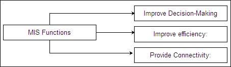
MIS Functions

The broad functions of MIS are as given below:
  1. To improve decision-making: MIS helps management by providing background information on a variety of issues and helps to improve the decision-making quality of management. The fast and accurate information supplied by MIS is leveraged by the managers to take quicker and better decisions thereby improving the decision-making quality and adding to the bottom line of the company.
  2. To improve efficiency: MIS helps managers to conduct their tasks with greater ease and with better efficiency. This reflects in better productivity for the company.
  3. To provide connectivity: MIS provides managers with better connectivity with the rest of the organization.
                                      Functions of MIS

Characteristics of MIS

Management information being a specialized information system conforms to certain characteristics. These characteristics are generic in nature. These characteristics remain more or less the same even when the technology around such management information system changes:

Management oriented

One important feature of MIS is that MIS is designed top-down. This means that the system is designed around the need felt by the management at different levels for information. The focus of the system is to satisfy the information needs of management.

Management directed

Since MIS is 'for the' management it is imperative that it also should have a very strong 'by the' management initiative. Management is involved in the designing process of MIS and also in its continuous review and up gradation to develop a good qualitative system. The system is structured as per directions factored by management. This helps in minimizing the gap between expectations of management form the system and the actual system.

Integrated

MIS is an integrated system. It is integrated with all operational and functional activities of management. This is an important characteristic and- requirement for a system to qualify as MIS. The reason for having an integrated system is that information in the managerial context for decision-making may be required from different areas from within the organization. If MIS remains a collection of isolated systems and each satisfying a small objective, then the integrated information need of managers will not be fulfiller. In order to provide a complete picture of the scenario, complete information is needed which only an integrated system can provide.

Common data flows

Through MIS the data being stored into the system, retrieved from the system, disseminated within the system or processed by the system can be handled in an integrated manner. The integrated approach towards data management will result in avoiding duplication of data, data redundancy and will help to simplify operations.

Strategic planning

MIS cannot be designed overnight. It requires very high degree of planning which goes into creating an effective organization. The reason for this kind of planning is to ensure that the MIS being built not only satisfies the information need of the managers today but can also serve the organization for the next five to ten years with modifications. Sometimes when the planning part is done away with, systems tend to perform well in the present but they tend to become obsolete with time. Planning helps to avoid this problem.

Bias towards centralization

MIS is required to give 'one version of the truth', i.e., it must supply the correct version of the latest information. There is a requirement for the data repository to be centralized. Centralized data management helps MIS to exercise version control as well as provide an integrated common view of data to the managers. In a non-centralized system, data will get entered, updated and deleted from the system from different locations. In such a case it becomes difficult to provide correct information to managers. For example, in a decentralized System if a person superannuates from an organization and his superannuating is only recorded in the human resource system but not communicated to the finance department system, then it is quite likely that his salary may be generated by the finance system for the next month. A centralized system where data in entered, updated and deleted from only one location does not suffer from such problems. In a centralized system, the superannuating employee's details are deleted from the master file from which all departments' access data, thereby eliminating the risk of generating his salary for the next month.